 |
PIAS Handleiding
2025
Programma voor de Integrale Aanpak van het Scheepsontwerp
|
 |
PIAS Handleiding
2025
Programma voor de Integrale Aanpak van het Scheepsontwerp
|
All active solids and wireframes can be rotated simultaneously with the action started from [Solids]→[Rotate Objects] or with the keys <Alt><O><R>. Objects can be activated and deactivated at any time by toggling their [Access] checkbox in the tree view.
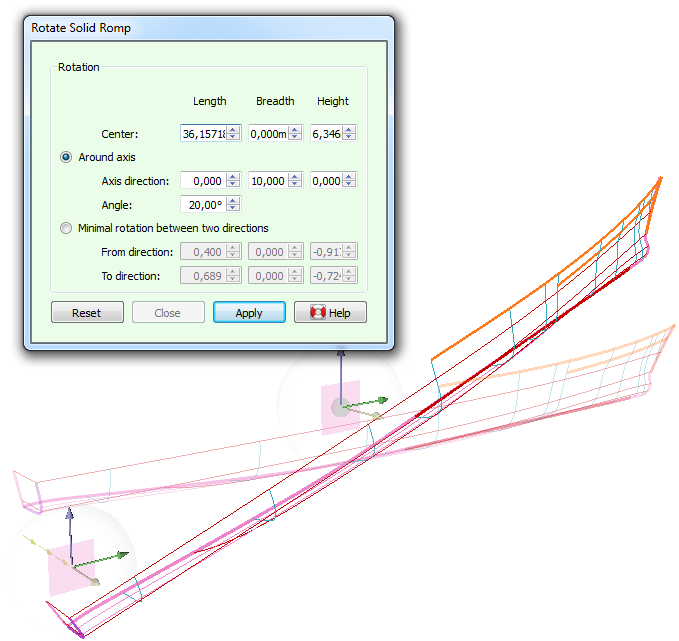
This action displays several draggers at the same time: There is one dragger for positioning a small white sphere which defines the center of rotation. In addition, depending on how the rotation is defined, there are one or two draggers for defining directions. Depending on the zoom level these may overlap each other, zooming in will help identify them.

The axis of rotation obviously passes through the center of rotation, in a given direction. The axis direction, together with the angle of rotation, can be defined in two ways.
By default the axis direction and angle of rotation are defined explicitly, with the option [Around axis]. The angle can be manipulated interactively on the action panel (see Numerical input), the axis direction can in addition be manipulated graphically using a directional dragger (see Dragging a direction vector). Note that the directional vector does not need to have its origin coincide with the center of rotation (see figure) which allows these values to be measured from the model by applying dragger snap ( Snapping to other points in the model).
Alternatively, the option [Minimal rotation between two directions] allows the axis direction and angle of rotation to be determined implicity. Given a vector pointing in a given direction it finds the rotation that makes it point in a second given direction. The axis of rotation is always perpendicular to these two vectors. Again, you are free to drag or snap the origin of these vectors independently, which makes it easy to extract directions from between existing points in the model.